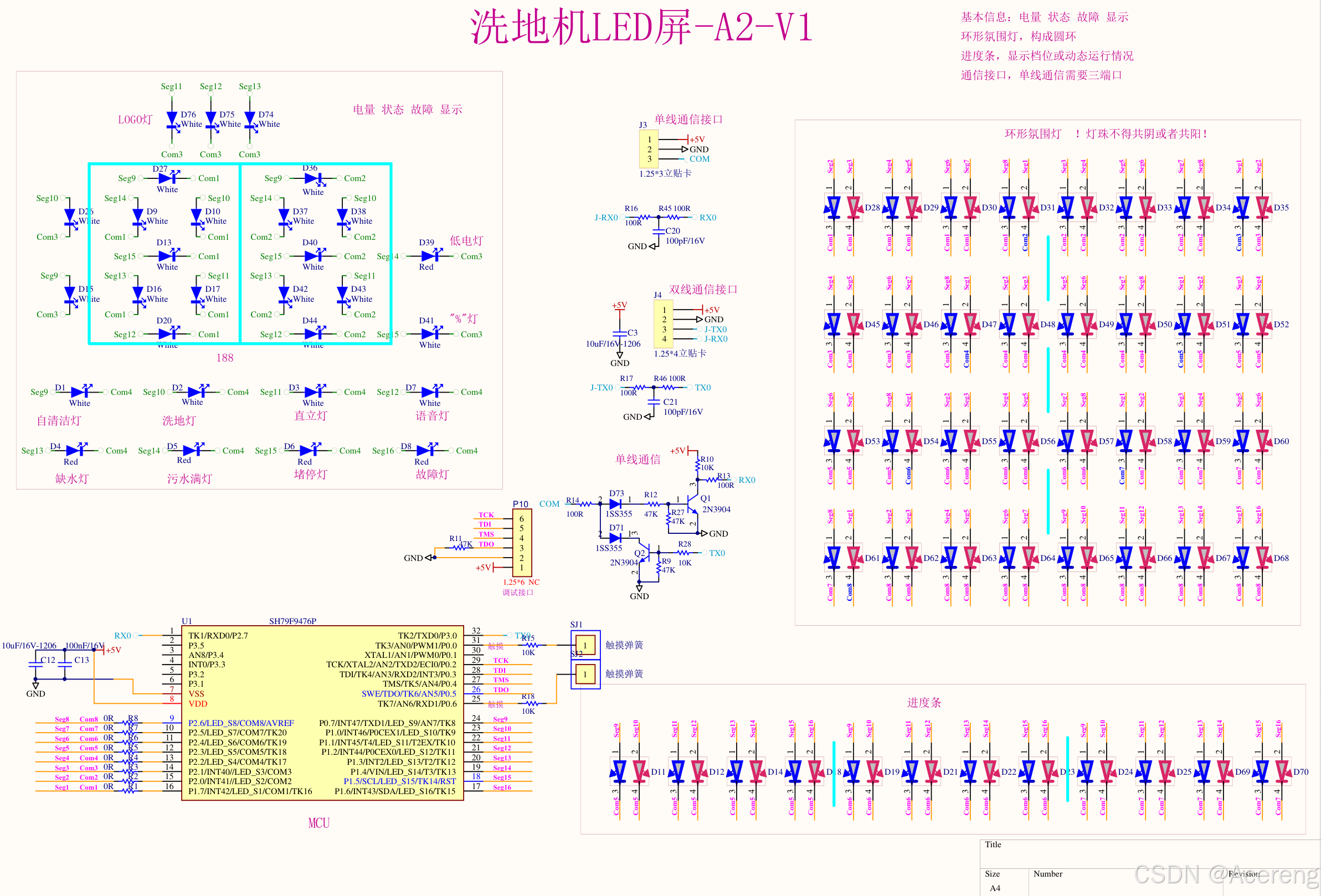
Driving 120 LEDs with 16 I/O Pins and 256-Level Individual Dimming
Overview
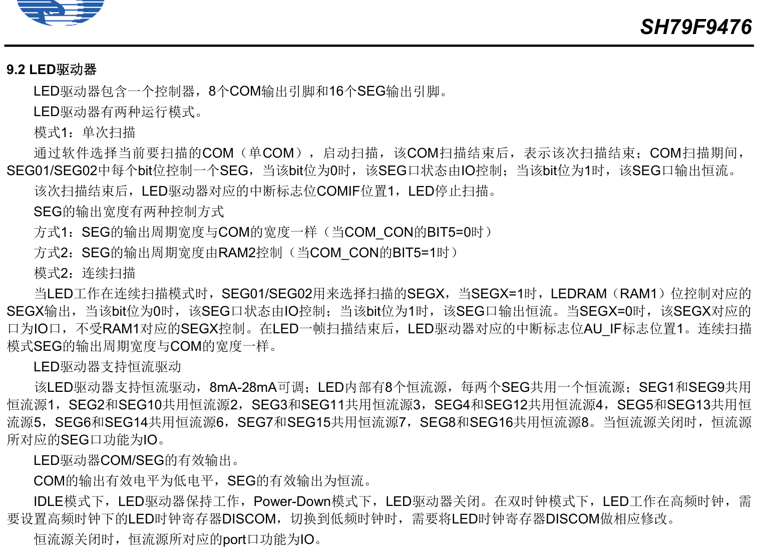
This implementation utilizes the LED driver RAM table within the microcontroller to achieve two distinct driving modes.
For breathing light effects, only Mode 1 is applicable: Single Scan using RAM2 table.
Mode 1 Operation
- Softawre Selection: The current COM line (single COM) is selected via software to initiate scanning.
- Scan Completion: When the COM line scanning finishes, the scan cycle ends.
- SEG Control: During COM scanning, each bit in SEG01/SEG02 controls one SEG line:
- Bit = 0: SEG line state controlled by I/O
- Bit = 1: SEG line outputs constant current
- Interrupt Flag: After scanning completes, the COMIF interrupt flag is set and LED scanning stops.
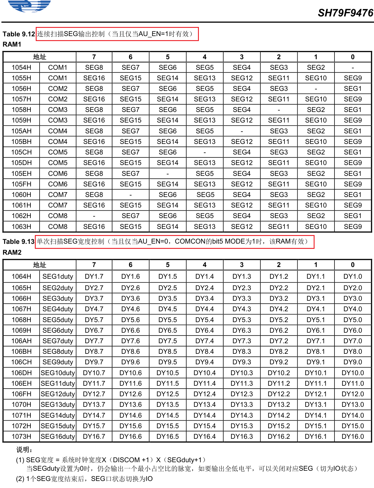
SEG Output Width Control
Two methods control SEG output width:
- Method 1: SEG output period equals COM width (when COM_CON BIT5 = 0)
- Method 2: SEG output period controlled by RAM2 (when COM_CON BIT5 = 1)
Interrupt Handler Implementation
In the COM output completion interrupt handler:
// Refresh current COM's 16 SEG data to RAM2 table
for (segment_index = 0; segment_index < 16; segment_index++) {
    *ram2_pointer = com_duty_buffer[segment_index]; // seg1~seg16
    ram2_pointer++; // Populates RAM2 sequentially to refresh SEG brightness duty
}

COM_CON |= 0x88; // Start next scan (GO bit)

// Prepare next COM's 16 SEG data
for (segment_index = 0; segment_index < 16; segment_index++) {
    com_duty_buffer[segment_index] = display_buffer[current_com][segment_index];
}
This refreshes the current COM's 16 SEG data to the RAM2 table for hardware LED refresh and prepares the next COM's data.
Main Loop Control
Simply modify the 8×16 display_buffer array in the main loop to control LED states.
Ghosting Issue and Solutino
Problem: Ghosting artifacts appeared, likely caused by duty cycle assignment to 0 during push-pull operations.
Solution: Adjusted the refresh program structure to eliminate ghosting.
Revised Interrupt Handler
void led_driver_isr(void) interrupt 8 {
    unsigned char units_digit = 0;
    unsigned char tens_digit = 0;
    unsigned char hundreds_digit = 0;

    _push_(INSCON);
    INSCON &= 0xBF; // Select special function register page 0

    seg_duty_pointer = RAM2_ADDRESS; // Assign RAM2 address to pointer
    COM_CON &= 0x38; // Clear COM output completion interrupt flag

    current_com++;

    // Battery level processing
    if (battery_percentage != 100) {
        units_digit = battery_percentage % 10;
        tens_digit = battery_percentage / 10;
        hundreds_digit = 0;
    } else {
        units_digit = 0;
        tens_digit = 0;
        hundreds_digit = 1;
    }

    // COM line selection and SEG configuration
    switch (current_com) {
        case 1: // COM1
#if (LED_COM_ENABLE & 0x01)
            COM_CON |= 0x00;
            SEG01 = 0xFF; // Select SEG1-8
            SEG02 = 0xFF; // Select SEG9-16
            set_segment(0, tens_digit, 250); // COM1 displays tens digit
            break;
#else
            current_com++;
#endif

        case 2: // COM2
#if (LED_COM_ENABLE & 0x02)
            COM_CON |= 0x01;
            SEG01 = 0xFF;
            SEG02 = 0xFF;
            set_segment(1, units_digit, 250); // COM2 displays units digit
            break;
#else
            current_com++;
#endif

        // Additional COM cases 3-8 follow similar pattern
        // ...

        case 8: // COM8
#if (LED_COM_ENABLE & 0x80)
            COM_CON |= 0x07;
            SEG01 = 0xFF;
            SEG02 = 0xFF;
#endif
            current_com = 0;
            break;
    }

    // Refresh current COM's SEG data to RAM2
    for (segment_index = 0; segment_index < 16; segment_index++) {
        *seg_duty_pointer = seg_duty_array[segment_index];
        seg_duty_pointer++;
    }

    COM_CON |= 0x88; // Start next scan

    // Load next frame data
    for (segment_index = 0; segment_index < 16; segment_index++) {
        seg_duty_array[segment_index] = display_buffer[current_com][segment_index];
    }

    _pop_(INSCON);
}
After eliminating ghosting, the final program achieves clean LED control.
Note: This implementation demonstrates driving LED panels for floor cleaning devices using Sino Wealth microcontrollers.
