SRv6 Best-Effort Simulation Experiment (ENSP)
SRv6 (Segment Routing IPv6) is a segment routing technology based on IPv6. It achieves flexible and efficient packet forwarding by embedding routing information in the extension fields of the IPv6 packet header. SRv6 borrows the concept of Segment Routing and applies it to IPv6 networks.
The core idea of SRv6 is to use programmable segments in the IPv6 address space to represent network paths. Each segment represents a specific node or link in the network. By arranging these segments in a specific order, SRv6 specifies the forwarding path of packets.
The advantages of SRv6 include:
- Flexibility: Administrators can define and configure flexible paths to adapt to various application and business requirements. By combining different segments, they can specify the exact path of packets, enabling precise traffic control and customized routing.
- Simplified network: SRv6 avoids the need for maintaining a large amount of state information in traditional routing protocols, making the network more concise and efficient. SRv6 nodes only need to care about the next segment, reducing complexity.
- Network programming: SRv6 provides a network-based programming model that allows the network to be programmed and automated based on application needs. Administrators can define various service chains, traffic engineering, and path optimization strategies.
- Scalability: SRv6 uses IPv6 address space as path identifiers, which has sufficient address resources to support large-scale network deployment and rapid expansion.
Application scenarios of SRv6 include:
- Traffic engineering: Flexible traffic engineering can be implemented to optimize packet forwarding paths based on application requirements and network status, achieving load balancing and congestion avoidance.
- Service chaining: SRv6 can define and manage service chains, combining different network services (e.g., firewalls, load balancers) into flexible service links.
- Network slicing: SRv6 can divide the physical network into multiple logical networks to provide indepandent network resources for different applications or users.
- Data center interconnection: SRv6 can interconnect data centers to build efficient and flexible cloud networks.
Note that SRv6 is a relatively new technology and is being deployed widely.
Experiment Process
Topology
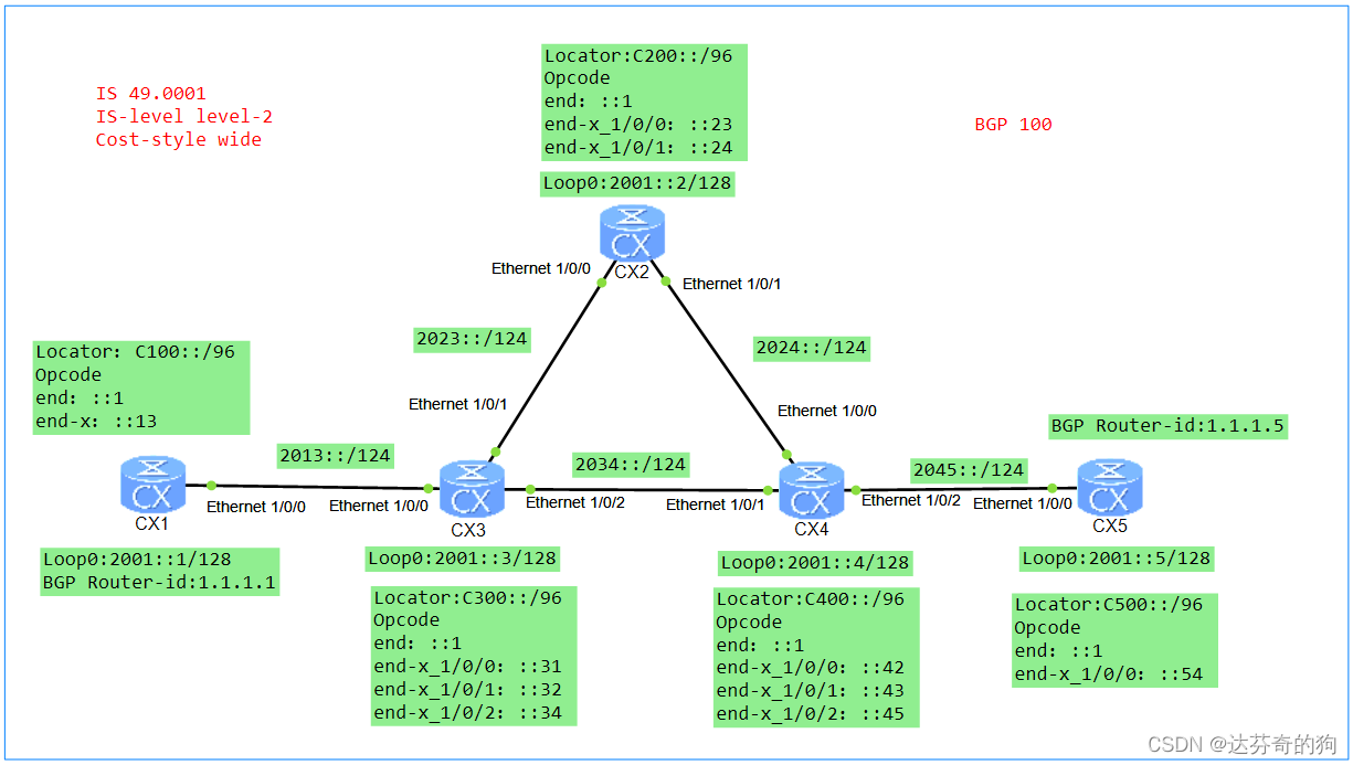
As shown in the figure, interface IPv6 addresses are labeled in the diagram. Locators are manually added to devices, Functions (also called Opcodes) are statically configured, and Arguments are not configured.
Note: When statically configuring SIDs, SIDs only occupy the static segment range. The static segment starts from 1, and the dynamic segment is set to 0. When dynamically allocating SIDs, SIDs occupy both dynamic and static segments. The dynamic segment starts from 1, and the static segment starts from 0. Using dynamically generated SIDs may cause changes upon device restart, which is not conducive to maintenance.
This experiment uses ISIS as the IGP, which supports both IPv4 and IPv6.
1. Configure ISIS and enable IPv6
First, configure ISIS and enable IPv6, then assign IPv6 addresses to interfaces, and finally enable ISIS on the interfaces.
[CX1]isis 1
[CX1-isis-1] is-level level-2
[CX1-isis-1] cost-style wide
[CX1-isis-1] network-entity 49.0001.0000.0001.00
[CX1-isis-1] is-name CX1
[CX1-isis-1] ipv6 enable topology standard

[CX1]undo dcn
[CX1]interface Ethernet1/0/0
[CX1-Ethernet1/0/0] undo shutdown
[CX1-Ethernet1/0/0] ipv6 enable
[CX1-Ethernet1/0/0] ipv6 address 2013::1/124
[CX1-Ethernet1/0/0] isis ipv6 enable 1

[CX1]interface LoopBack0
[CX1-LoopBack0] ipv6 enable
[CX1-LoopBack0] ipv6 address 2001::1/128
[CX1-LoopBack0] isis ipv6 enable 1
[CX2] undo dcn
[CX2]isis 1
[CX2-isis-1] is-level level-2
[CX2-isis-1] cost-style wide
[CX2-isis-1] network-entity 49.0001.0000.0002.00
[CX2-isis-1] is-name CX2
[CX2-isis-1] ipv6 enable topology standard
[CX2-isis-1]quit

[CX2]interface Ethernet1/0/0
[CX2-Ethernet1/0/0] undo shutdown
[CX2-Ethernet1/0/0] ipv6 enable
[CX2-Ethernet1/0/0] ipv6 address 2023::2/124
[CX2-Ethernet1/0/0] isis enable 1
[CX2-Ethernet1/0/0] isis ipv6 enable 1
[CX2-Ethernet1/0/0]quit

[CX2]interface Ethernet1/0/1
[CX2-Ethernet1/0/1] undo shutdown
[CX2-Ethernet1/0/1] ipv6 enable
[CX2-Ethernet1/0/1] ipv6 address 2024::2/124
[CX2-Ethernet1/0/1] isis ipv6 enable 1

[CX2]interface LoopBack0
[CX2-LoopBack0] ipv6 enable
[CX2-LoopBack0] ipv6 address 2001::2/128
[CX2-LoopBack0] isis ipv6 enable 1
[CX3] undo dcn
[CX3]isis 1
[CX3-isis-1] is-level level-2
[CX3-isis-1] cost-style wide
[CX3-isis-1] network-entity 49.0001.0000.0003.00
[CX3-isis-1] is-name CX3
[CX3-isis-1] ipv6 enable topology standard
[CX3-isis-1] quit

[CX3]interface Ethernet1/0/0
[CX3-Ethernet1/0/0] undo shutdown
[CX3-Ethernet1/0/0] ipv6 enable
[CX3-Ethernet1/0/0] ipv6 address 2013::3/124
[CX3-Ethernet1/0/0] isis ipv6 enable 1
[CX3-Ethernet1/0/0]quit

[CX3]interface Ethernet1/0/1
[CX3-Ethernet1/0/1] undo shutdown
[CX3-Ethernet1/0/1] ipv6 enable
[CX3-Ethernet1/0/1] ipv6 address 2023::3/124
[CX3-Ethernet1/0/1] isis ipv6 enable 1
[CX3-Ethernet1/0/1]quit

[CX3]interface Ethernet1/0/2
[CX3-Ethernet1/0/2] undo shutdown
[CX3-Ethernet1/0/2] ipv6 enable
[CX3-Ethernet1/0/2] ipv6 address 2034::3/124
[CX3-Ethernet1/0/2] isis ipv6 enable 1
[CX3-Ethernet1/0/2] quit

[CX3]interface LoopBack0
[CX3-LoopBack0] ipv6 enable
[CX3-LoopBack0] ipv6 address 2001::3/128
[CX3-LoopBack0] isis ipv6 enable 1
[CX4]isis 1
[CX4-isis-1] is-level level-2
[CX4-isis-1] cost-style wide
[CX4-isis-1] network-entity 49.0001.0000.0004.00
[CX4-isis-1] is-name CX4
[CX4-isis-1] ipv6 enable topology standard

[CX4] undo dcn
[CX4]interface Ethernet1/0/0
[CX4-Ethernet1/0/0] undo shutdown
[CX4-Ethernet1/0/0] ipv6 enable
[CX4-Ethernet1/0/0] ipv6 address 2024::4/124
[CX4-Ethernet1/0/0] isis ipv6 enable 1

[CX4]interface Ethernet1/0/1
[CX4-Ethernet1/0/1] undo shutdown
[CX4-Ethernet1/0/1] ipv6 enable
[CX4-Ethernet1/0/1] ipv6 address 2034::4/124
[CX4-Ethernet1/0/1] isis ipv6 enable 1

[CX4]interface Ethernet1/0/2
[CX4-Ethernet1/0/1] undo shutdown
[CX4-Ethernet1/0/1] ipv6 enable
[CX4-Ethernet1/0/1] ipv6 address 2045::4/124
[CX4-Ethernet1/0/1] isis ipv6 enable 1

[CX4]interface LoopBack0
[CX4-LoopBack0] ipv6 enable
[CX4-LoopBack0] ipv6 address 2001::4/128
[CX4-LoopBack0] isis ipv6 enable 1
[CX5]isis 1
[CX5-isis-1] is-level level-2
[CX5-isis-1] cost-style wide
[CX5-isis-1] network-entity 49.0001.0000.0005.00
[CX5-isis-1] is-name CX5
[CX5-isis-1] ipv6 enable topology standard

[CX5] undo dcn
[CX5]interface Ethernet1/0/0
[CX5-Ethernet1/0/0] undo shutdown
[CX5-Ethernet1/0/0] ipv6 enable
[CX5-Ethernet1/0/0] ipv6 address 2045::5/124
[CX5-Ethernet1/0/0] isis ipv6 enable 1

[CX5]interface LoopBack0
[CX5-LoopBack0] ipv6 enable
[CX5-LoopBack0] ipv6 address 2001::5/128
[CX5-LoopBack0] isis ipv6 enable 1
After configuration, check ISIS neighbors and routes.
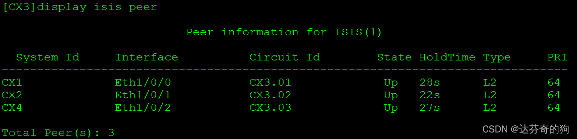
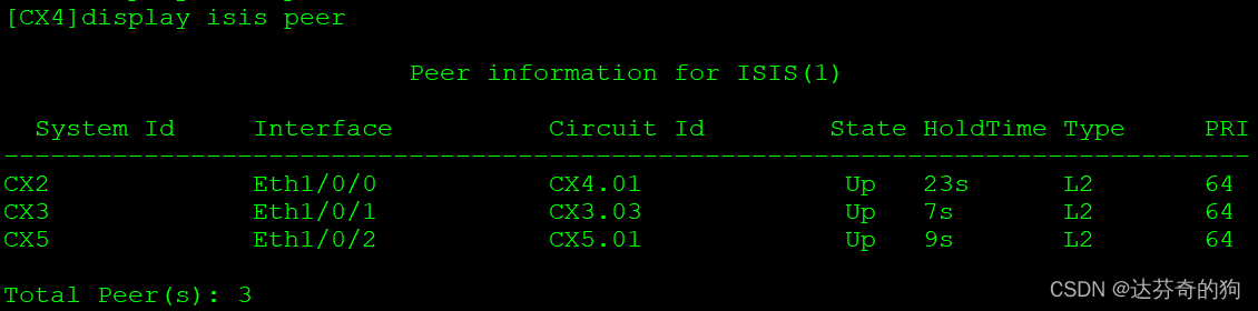
All neighbors are established as Level-2.
To verify that all interfaces are configured with ISIS, use the following command:
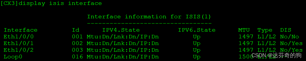
Then check ISIS routes and verify reachability.
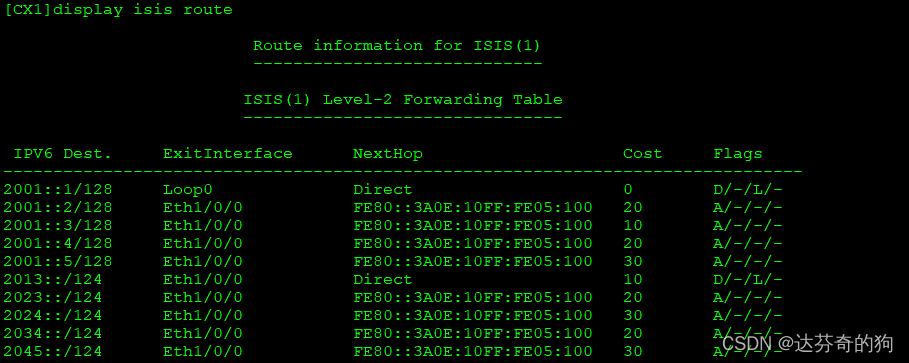
All device interfaces and loopback routes are learned. Next, configure SRv6.
2. Enable SRv6 and configure SIDs
Enable SRv6 and create SRv6 SIDs. This experiment uses static configuration. Below is the structure of SRv6 ID and functions.
Locator Configuration Format:
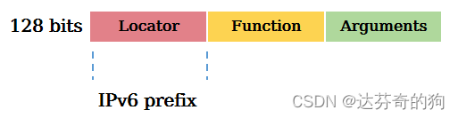
Locator function: Identifies a network node and is used for routing packets to that node, enabling addressability of network instructions.
Function Configuration Format:
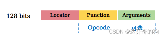
Function function: Identifies the forwarding action to be executed. Different forwarding behaviors are identified by different Functions, such as End, End.X, End.DX4, End.DX6 defined in RFC.
| Typee | Description | Protocol | Type |
|---|---|---|---|
| End | Endpoint SID, identifies a destination node; action: update IPv6 DA, lookup IPv6 FIB | IGP | Path SID |
| End.X | Layer 3 cross-connect Endpoint SID, identifies a link; action: update IPv6 DA, forward from bound interface | IGP | Path SID |
| End.DT4 | PE-type Endpoint SID for IPv4 VPN instance; action: decapsulate and lookup IPv4 VPN routing table | BGP | Service SID |
| End.DT6 | PE-type Endpoint SID for IPv6 VPN instance; action: decapsulate and lookup IPv6 VPN routing table | BGP | Service SID |
End is equivalent to node SID in SR, End.X is equivalent to link SID. These SIDs are carried and forwarded via ISIS routing tables.
Configure Locators:
Note: Locators should be unique within the SR domain.
[CX1]segment-routing ipv6
[CX1-segment-routing-ipv6] encapsulation source-address 2001::1
[CX1-segment-routing-ipv6] locator huawei ipv6-prefix C100:: 96 static 16
[CX1-segment-routing-ipv6-locator]  opcode ::1 end
[CX1-segment-routing-ipv6-locator]  opcode ::13 end-x interface Ethernet1/0/0 nexthop 2013::3
[CX2-segment-routing-ipv6]segment-routing ipv6
[CX2-segment-routing-ipv6] encapsulation source-address 2001::2
[CX2-segment-routing-ipv6] locator huawei ipv6-prefix C200:: 96 static 16
[CX2-segment-routing-ipv6-locator]  opcode ::1 end
[CX2-segment-routing-ipv6-locator]  opcode ::23 end-x interface Ethernet1/0/0 nexthop 2023::3
[CX2-segment-routing-ipv6-locator]  opcode ::24 end-x interface Ethernet1/0/1 nexthop 2024::4
[CX3]segment-routing ipv6
[CX3-segment-routing-ipv6] encapsulation source-address 2001::3
[CX3-segment-routing-ipv6] locator huawei ipv6-prefix C300:: 96 static 16
[CX3-segment-routing-ipv6-locator]  opcode ::1 end
[CX3-segment-routing-ipv6-locator]  opcode ::31 end-x interface Ethernet1/0/0 nexthop 2013::1
[CX3-segment-routing-ipv6-locator]  opcode ::32 end-x interface Ethernet1/0/1 nexthop 2023::2
[CX3-segment-routing-ipv6-locator]  opcode ::34 end-x interface Ethernet1/0/2 nexthop 2034::4
[CX4]segment-routing ipv6
[CX4-segment-routing-ipv6] encapsulation source-address 2001::4
[CX4-segment-routing-ipv6] locator huawei ipv6-prefix C400:: 96 static 16
[CX4-segment-routing-ipv6-locator]  opcode ::1 end
[CX4-segment-routing-ipv6-locator]  opcode ::42 end-x interface Ethernet1/0/0 nexthop 2024::2
[CX4-segment-routing-ipv6-locator]  opcode ::43 end-x interface Ethernet1/0/1 nexthop 2034::3
[CX4-segment-routing-ipv6-locator]  opcode ::45 end-x interface Ethernet1/0/2 nexthop 2045::5
[CX5]segment-routing ipv6
[CX5-segment-routing-ipv6] encapsulation source-address 2001::5
[CX5-segment-routing-ipv6] locator huawei ipv6-prefix C500:: 96 static 16
[CX5-segment-routing-ipv6-locator]  opcode ::1 end
[CX5-segment-routing-ipv6-locator]  opcode ::54 end-x interface Ethernet1/0/0 nexthop 2045::4
Check the node and link SIDs:
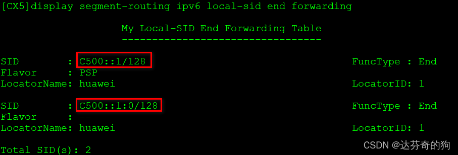
There are two node SIDs: one statically configured, and one dynamically generated. The static one has an additional behavior of PSP (Penultimate Segment Pop). Understanding PSP:
| Additional Behavior | Description | Attached to |
|---|---|---|
| PSP | Remove SRH at penultimate Endpoint node | End, End.X, End.DT2, End.DT4, End.DT6 |
| USP | Remove SRH at last Endpoint node | End, End.X, End.DT2, End.DT4, End.DT6 |
| USD | Decapsulate outer IPv6 header at last Endpoint node | End, End.X, End.DT2, End.DT4, End.DT6 |
PSP is similar to penultimate hop popping in MPLS.
Now check link SIDs:
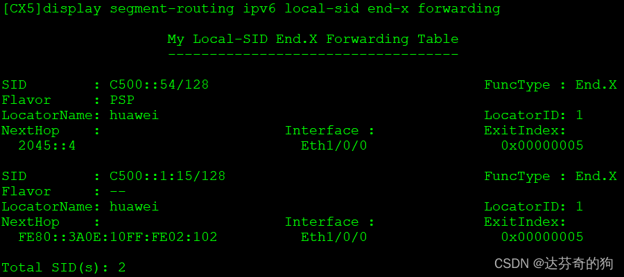
Similarly, two link SIDs (static and dynamic) appear. For CX5, only one link exists.
We need to advertise the Locator via ISIS and disable dynamic SID generation.
[CX1]isis 1
[CX1-isis-1] segment-routing ipv6 locator huawei auto-sid-disable
[CX2]isis 1
[CX2-isis-1] segment-routing ipv6 locator huawei auto-sid-disable
[CX3]isis 1
[CX3-isis-1] segment-routing ipv6 locator huawei auto-sid-disable
[CX4]isis 1
[CX4-isis-1] segment-routing ipv6 locator huawei auto-sid-disable
[CX5]isis 1
[CX5-isis-1] segment-routing ipv6 locator huawei auto-sid-disable
Check SIDs again:
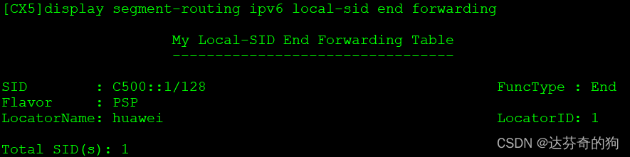
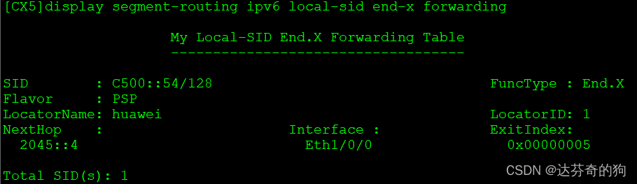
Dynamic SIDs have disappeared. Check ISIS IPv6 routing table:
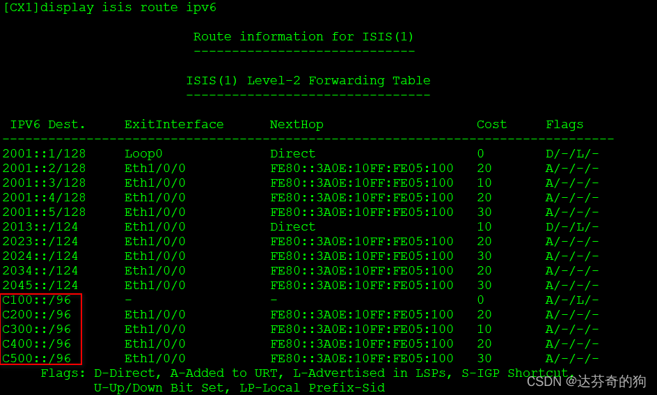
Locators are successfully advertised via ISIS.
Test SID connectivity along path 1-3-2-4-5:
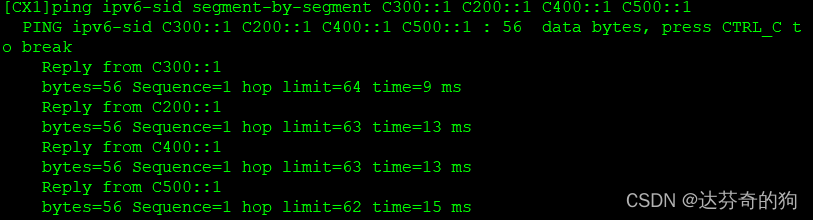
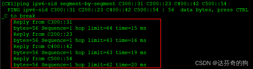
All node and link SIDs are reachable.
3. Create VPN instance between CX1 and CX5
Create VPN instance, bind to loopback1, establish BGP peers using IPv6, associate SRv6 Locator and enable BE tunnel.
Create VRF and bind:
[CX1]ip vpn-instance huawei
[CX1-vpn-instance-huawei] ipv4-family
[CX1-vpn-instance-huawei-af-ipv4]  route-distinguisher 100:1
[CX1-vpn-instance-huawei-af-ipv4]  vpn-target 100:1 export-extcommunity
[CX1-vpn-instance-huawei-af-ipv4]  vpn-target 100:1 import-extcommunity

[CX1]interface LoopBack1
[CX1-LoopBack1] ip binding vpn-instance huawei
[CX1-LoopBack1] ip address 11.11.11.11 255.255.255.255
[CX5]ip vpn-instance huawei
[CX5-vpn-instance-huawei] ipv4-family
[CX5-vpn-instance-huawei-af-ipv4]  route-distinguisher 100:1
[CX5-vpn-instance-huawei-af-ipv4]  vpn-target 100:1 export-extcommunity
[CX5-vpn-instance-huawei-af-ipv4]  vpn-target 100:1 import-extcommunity

[CX5]interface LoopBack1
[CX5-LoopBack1] ip binding vpn-instance huawei
[CX5-LoopBack1] ip address 55.55.55.55 255.255.255.255
BGP peer configuration:
[CX1]bgp 100
[CX1-bgp] router-id 1.1.1.1
[CX1-bgp] peer 2001::5 as-number 100
[CX1-bgp] peer 2001::5 connect-interface LoopBack0
[CX1-bgp] ipv4-family vpnv4
[CX1-bgp-af-vpnv4]  policy vpn-target
[CX1-bgp-af-vpnv4]  peer 2001::5 enable
[CX1-bgp-af-vpnv4]  peer 2001::1 prefix-sid
[CX1-bgp-af-vpnv4] quit
[CX1-bgp] ipv4-family vpn-instance huawei
[CX1-bgp-huawei]  import-route direct
[CX1-bgp-huawei]  segment-routing ipv6 locator huawei
[CX1-bgp-huawei]  segment-routing ipv6 best-effort
[CX5]bgp 100
[CX5-bgp] router-id 1.1.1.5
[CX5-bgp] peer 2001::1 as-number 100
[CX5-bgp] peer 2001::1 connect-interface LoopBack0
[CX5-bgp] ipv4-family vpnv4
[CX5-bgp-af-vpnv4]  policy vpn-target
[CX5-bgp-af-vpnv4]  peer 2001::1 enable
[CX5-bgp-af-vpnv4]  peer 2001::1 prefix-sid
[CX5-bgp-af-vpnv4] quit
[CX5-bgp] ipv4-family vpn-instance huawei
[CX5-bgp-huawei]  import-route direct
[CX5-bgp-huawei]  segment-routing ipv6 locator huawei
[CX5-bgp-huawei]  segment-routing ipv6 best-effort
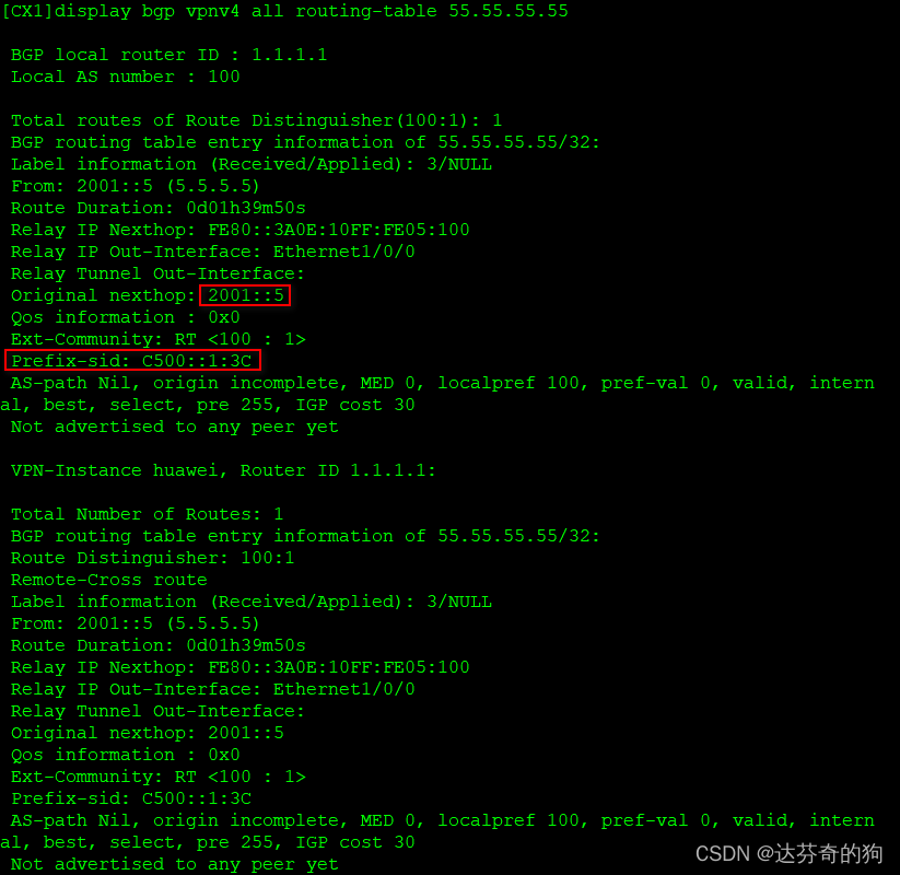
Check BGP neighbors and learned routes:
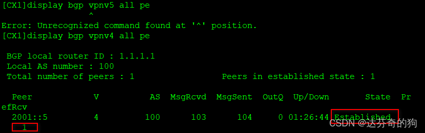
Neighbor established and route learned.
Check VPN instance routing table:
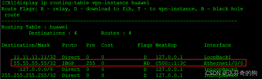
Route added successfully.
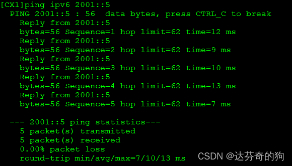
Test connectivity and capture packets:
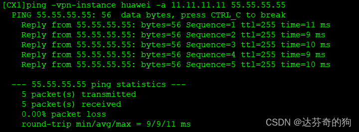
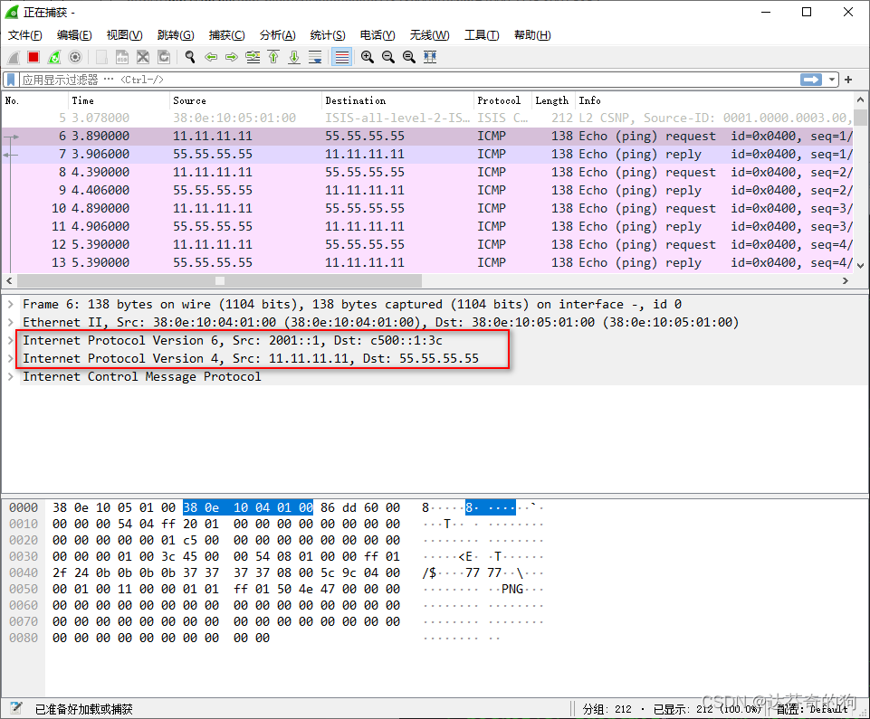
Connectivity is fine. The inner layer addresses are loopback addresses of both ends. The outer source address is CX1's loopback, destination is CX5's Prefix-ID assigned for the route.
This concludes the experiment.
